(E3) Electric CircuitsAt this point we might start drawing diagrams of electrical circuits. A line represents a wire (or in electricians' lingo, "an electrical conductor"). When two lines in the diagram cross and they are connected at the crossing point, the point is usually drawn heavy, or with a small dark circle. If they cross without being connected, the crossing is sometimes marked by a small arc in one wire, crossing the other like a bridge. A break in the wire with a short pivoted end is a switch, regardless of the way it actually works (the diagram suggests a "knife switch").
(drawings)
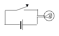
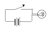
An electric cell is marked by two parallel lines, perpendicular to the connected wires--a short fat one (the negative side) and a long thin one (the positive one--the button end, in the usual dry cell), each a symbol for one of the different materials (e.g. metals) used in some batteries. (Do not confuse this with a capacitor, marked by two equal parallel lines.) With an obvious symbol for an electric lightbulb, the circuit of a simple flashlight can therefore be drawn thus:

However, the number of cells may be large, so the symbol for an electric cell or for a 2-cell battery is often used for any battery--with the number of volts indicated in writing. If two different batteries are part of the same diagram, the one with higher voltage could be drawn with a larger number of plates.
A resistance (or a "resistor, a device introducing a specific resistance) is drawn as a zig-zag line, and its resistance in ohms is denoted by the Greek letter Ω (capital Omega). This way one may draw:
An Edison-type lightbulb, emitting light from a hot glowing wire, is of course a resistance too, and will be drawn as such in circuit diagrams, unless we want to emphasize its special role. Lamps using a hot gas (e.g. "fluorescent") or relying on solid-state effect have more complex behavior
More on Ohm's LawOhm's law holds separately for each part of the circuit. If V is the voltage drop between any two points of the circuit, and R is the resistance between them, then the current I between these points satisfies Indeed, that is the way the law is usually used. In the drawing above, for instance, Ohm's law is applied (when the switch closes) between points A and B. What happens inside the battery (which is also part of the circuit) is not taken into account. 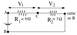
Imagine for example a circuit driven by a 12-volt battery (below), in which two resistances R1 = 3 Ω and R2 = 9 Ω follow each other as drawn ("connected in series"). The total voltage drop from A to B equals V = 12 volt, and similar to a pressure drop in a pipe, it can be viewed as the sum of a voltage drop V1 from A to C (across R1), plus a voltage drop V2 from C to B (across R2). Of course Ohm's law holds separately for the currents I1 and I2 flowing in the separate parts: In this case, of course, the same current flows through all parts of the circuit, and denoting it by I, we get That equality leads to further conclusions, and we will return to them later. To remember
Optional PuzzlesNote: You may assume that the current in the examples below comes from a battery. Actually, however, results derived here remain valid with alternating currents. Answers and more are presented here. (1) A 3-way switch is one that in one position connects the wire at A to the one at B, in the other position it connects it to the one at C. There is no other position--A must be connected to one or the other, it cannot be left open (as in an ordinary switch). 
Now: You are given a box with an electric lightbulb and two switches (drawing).The power source is either a battery inside or a power cord (makes no diference). Either switch can turn the light on or off. You can turn it on and off with the same switch, or on with one and off to the other. 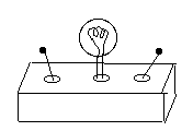
Draw a diagram of a possible way of wiring the inside of the box, using 3-way switches. Hint: Since both switches have the same features, try to have them wired similarly! Note: This wiring has its practical use. Suppose your home has a long stairway leading to the basement, which also has an exit to the garage. One switch might be on top of the stairs, one near the exit door. Going to the garage you turn on the light at the basement entrance and off at the exit, while coming back, you use the switches in reverse order. If you are just going to the basement to fetch something, you can turn the light on and off at the same location. 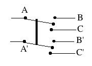
(2) A 4-way switch (drawing) contains two 3-way switches working together, though the user sees just one handle, same as in an ordinary switch. (The dark line is a mechanical connection, a bar making both switches move together. It is not a wire and does not carry a current). In one position, (A,A') are electrically connected to (B,B'), in the other they are connected to (C,C'). (drawing) A 4-way switch may be wired as a reversing switch ("commutator"), as shown in the drawing. Only two wires, D and D', go out of it; the curving wire is not connected to D. In one position, A is connected to D and A' to D'. In the other, the connections are reversed: A is connected to D' and A' to D. 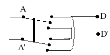
Rather than draw all connections, a reversing switch here will be drawn as a square with crossing lines (drawing below),
|


 The question: