By common convention, a resistor (with no other electrical properties) is indicated by a zig-zag line, with the value of the resistance indicated by
Ω , the capital Greek letter omega. (kilo-ohms or thousands of ohms are indicated by kΩ, mega-ohms or millions of ohms by MΩ ; the larger the resistance, the less current is allowed to trickle through it!)
 Notice that only voltage difference counts. In the above formulas, V really means "the voltage difference between the ends of the resistor." Put differently, the value assigned to the voltage (or "electric potential") at any point is generally only defined relative to other points. The ambiguity can be removed by choosing--for the purpose of calculations--one point to have voltage zero. In practical circuits, this is usually a point connected to the ground which, though not always as good a conductor as metal, is large enough to maintain a constant voltage that can serve as reference. In diagrams the ground is marked by a number of short horizontal lines, whose length decreases towards bottom so that they fill the space of a triangle.
In the diagram above, suppose the resistance is R=12Ω and when the switch is closed, the voltage at the right end of the resistor is V=9 volt. The other side of the resistor is grounded and the current is therefore
Another example, with an AC source and 3 resistors in series, is shown above. In an AC circuit, the voltage constantly changes and reverses polarity, and the value of 110 volt is really some sort of average (implying that 110V DC would deliver just as much energy). But because simple resistors handle DC and AC the same way, we may just as well pretend we have 110V DC.
Rotating control knobs on a radio or another instrument are likely to be connected to voltage dividers. The sliding contact C (arrowhead) can tap any voltage between V (when it touches A) and zero (when it touches B), and accordingly adjust the loudness of the sound, the brightness of the display or some other output.
Often the sliding contact goes to the input of an amplifier, so that it draws only a small current and does not create an appreciable variation of the energy demand. If only A and C are connected, this becomes a variable resistor, but then the power drawn varies widely with the setting. Variable resistors are marked in circuit diagrams by a zig-sag line for the resistor, crossed diagonally by an arrow.
Resistors are important elements in many devices. In a radio, currents are small and do not generate much heating, so resistors are often small plastic cylinders from whose ends connecting wires stick out. The resistor element is very much like the lead of a pencil, which conducts electricity by containing graphite, a form of carbon. Here the carbon may be finely mixed with a non-conducting substance, to control resistivity, or a conducting layer is deposited on the core.
"Wire wound" resistors have a special wire wound around a ceramic tube, covered with insulating glaze. They tend to be more stable and can take more heating, i.e. larger currents.
Most probably because you wired both lamps in series, not in parallel, so that the same current passes through both and each gets only 55 volts. Want to be sure? Unscrew one--the other should go out, too.
Of course, the total current you can draw from a home circuit is limited. If you connect too many lights and appliances, or somehow connect wires with opposite voltages directly (a "short circuit" with very little resistance), your circuit will draw so much power that your wiring gets dangerously hot. In most cases, a fuse will blow or a circuit breaker (to be discussed later) will cut the power, and the circuit will go dark. That will be your warning--before an excessive current melts your wiring, burns insulation or perhaps starts a house fire. Newspaper reports of fires often end with "...the fire chief believes the fire had an electrical origin": that is how it happens.
To derive the current drawn by a more complicated circuit, you can often start by replacing combinations of resistors with equivalent resistances. For instance, with the circuit shown here
 you first replace the two resistors in parallel with their equivalent single resistance R4
The above circuit (conceptually, not in actual values) may be viewed as representing the circuit of a car, with R3=4Ω the internal resistance of the battery (actual value probably much less), and R1=20Ω the resistance of the headlights, which draw a moderate current. Some voltage may drop while overcoming R3, but not much. However, when the starter engine is connected (represented by R2=5Ω) the effective load with Ri=4Ω equals the internal resistance of the battery, and therefore only half the available voltage appears across the circuit AB of the headlights, and those lights dim briefly, as is often observed.
Three currents emerge from A, each carrying 1/3 of the total current I and satisfying
The heating wires in an electric toaster, a room heater or an electric oven operate in a similar way, but only get red-hot.
The heat which electricity produces can be the source of danger. Two wires usually connect a house to the power station: in one electricity may be said to flow in, in the other out. Usually, the connection between them in the house also includes some load--e.g. a resistance or motor--which limits the current they draw.
Electric Codes and the Grounding of Wires
Electrical codes exist in all US states (and in countries all over the world), specifying standards which electric wiring must satisfy. In new homes, new plants and renovated construction, an official inspector examines the wiring (for a fee) to make sure it conforms to all rules of the code. If so, a license is issued, without which no insurance company will insure the construction against fire. The regulations are detailed, and professional electricians must be familiar with them. In many localities homeowners may work on the wiring of their own homes, but they too must follow the code.
All wires that carry current must have an insulation sufficient to hold back their voltage--you may not use telephone wire to carry 110 volts house current. In addition, a third bare (un-insulated) "ground wire" must follow all electrical lines, connected to all outlets and also to water pipes, and in one place, to the white "return wire." "Grounding the system" in this fashion protects users from leakages due to faulty insulation, for the following reason.
Strictly speaking, the flow in a water pipe is not driven by pressure, but the pressure difference between its ends. The air we breathe has a pressure of one atmosphere, but that pressure alone doesn't make it move anywhere: to move air requires a difference in air pressure between two points. Similarly, a voltage V itself will not move electric current through a wire: you need a high voltage at one end, and a low voltage at the other. Only voltage differences can drive a current.
The "value of the voltage" at any point in the circuit only becomes meaningful after we decide that some reference point in the circuit has "voltage zero" (and for purpose of calculation, any point may be chosen). Compare this with elevations on a map: only after choosing a reference point where the elevation is zero (usually, at sea level) can the values of other elevations be assigned values. If a different reference point were chosen (say, the top of the US Capitol dome in Washington), all those numbers would change.
The ground is a weak conductor, and is usually at a single voltage--and our bodies, walking on it, also have that voltage. The electric circuit has two wires--a black "hot" wire in which (by common convention, with alternating currents) the current is said to flow into the house, and a white "return" wire by which it is said to flow out again.
(Actually, AC sloshes back and forth, and each wire is positive half the time, negative half the time. But only the black line is assumed to have a direct connection to the power station.)
If neither of the wires is connected to the ground, then the voltage of either wire, relatively to the ground, is not defined. If our finger touches one of the wires, nothing will happen: that point will be at the same voltage of the ground, but in the absence of any voltage difference, no current flows through the finger.
However, suppose current leaks somewhere--because of imperfect insulation or because of water that leaked in. The leak has already established which part of the circuit is at the ground voltage--and if the wire we touch does not belong to that part, a current will flow from it through the finger to the ground. In some cases the leak is small and its current is just annoying--you touch a metal appliance and your fingers tingle. But with a big leak it can be downright dangerous.
To prevent this the circuit is grounded--the white wire is connected (at one selected spot) to the bare copper wire, and that bare wire is connected to the "ground"--to water pipes or to a metal stake driven deep into the ground. In the image here, the grounding wire is covered with an insulating sheath--in one section separated (by weathering) from the wire itself--leading to a buried stake in a clump of poison ivy. The grounding wire is connected to all exposed parts of the circuit--to the metal boxes enclosing switches and all wire connections (a usual code requirement), as well as to metal housings of machinery and appliances. We then know they are safe to touch: only the black "hot" wire can give shock.
The third prong on electric plugs of appliances connects their grounding to that of the outlet. Note also that power prongs usually differ from each other ("are polarized"): the one which is slightly wider connects to the "hot" side. Only appliances completely encased in an insulator may dispense with these rules.
To remember:
All wiring in the home must meet the standards of the national electrical code, protecting users from fire and electrical shock. For instance, the code prescribes insulation standards and requires (usually) that all connections occur inside metal boxes. One important precaution is the "grounding" of all circuits and their metal enclosures, connecting them to the ground (e.g. water pipes) and also (at one place in the house) to the white ("return") wiring. That assures that people handling appliances are safe from shock as long as they do not touch the "hot" wire.
|
(8) Electric Power
Closed Circuits
One big difference exists between our use of water and our use of electricity. Water indeed enters our homes along pipes, much the way electricity enters by wires. However, water is used in many different ways--cooking, washing, flushing waste, watering plants, adding humidity to the air. While the sewage pipes carry at least some of it out, the way it departs is not really a mirror image of the way it arrives.
The way electricity leaves is essentially a mirror image of the way it arrives. True, in home wiring one side is "grounded" to the water lines and/or to metal stakes in the ground, but this is done for safety reasons, as discussed elsewhere. The wiring itself is symmetric: the "hot" wires that bring current into the house, covered in black or red insulation, are always matched by "return" wires that carry it back out, grounded and covered with white or green insulation. Electric charge enters and leaves at equal rates. As will be seen, it is pretty hard to store more than tiny amounts of electric charge.
What the current does provide, between its coming and going, is
energy .
Flow of water or oil can also, in principle, supply energy (and is sometimes so used--search the internet about hydraulic machinery). Imagine electric power did not exist, and we needed something to drive machinery in the home--fans, tools, refrigerators, kitchen appliances and so forth. One way to get that energy would be to lead into the house a second system of water pipes, a closed system which is completely symmetric (drawing). Any water entering at high pressure P1 leaves again at a lower pressure P2, without leaving the system (oil or compressed air could also serve). Connected to the pipes would be little water wheels, each with its on-off faucet, each with a shaft connected to part of the home's machinery, and the flow of water would turn the wheels. (Oscillating garden sprinklers actually do contain small waterwheels, to make them spray back and forth, and cover a rectangular area). Electricity, at least where it turns motors, acts very much like that.
To remember:
Electric circuits are symmetric: any electric charge that enters is matched by an equal one that leaves. What is used is the energy of the current. A closed system of pipes carrying water (or air) under pressure could in principle serve the same way, entering the house at high pressure, leaving at low pressure, and turning small waterwheels (controlled by built-in faucets) wherever power was needed.
(Ever seen a humorous plaque "All electrons used in this device are recycled"?)
|
Watt's the Power?
How much power W--that is, how much energy per second--is obtained from such a water wheel? We may guess it would be proportional to F, the amount of water flowing through it each second: double F and you double the power.
We may also guess that it would be proportional to the pressure drop P = P1 – P2 which drives the wheel. Thus
W = k F P
with k some constant factor, depending on the efficiency of the water wheel and also on the units in which F, P and W are measured. The efficiency factor may be ignored if W equals all the power produced, the useful power extracted from the wheel plus the power wasted by the friction of the machinery and the water, which turns into heat. (For more about "Pelton wheels" driven by water, see here.)
For water wheels, the above formula is just a guess--W may be not be proportional to P but be derivable by some complicated expression involving P. The analogous formula for the power delivered by electric currents, however, holds exactly. If W equals all the power (see above) and common units are used, the factor k is not needed, and we get
W = I V
If I is measured in ampéres and V in volts, then W is measured in watts (and now you also know the reason for using the letter W).
How much is one watt? It is defined as 1 joule per second (see here
for more about the joule: to lift a kilogram 10 centimeters takes about one joule). For comparison, 736 watt equal one horsepower (HP), and the output of the electric blower on your furnace blower is 1/4 or 1/3 HP. An athletic human can provide about 0.1 HP and a horse... actually, the steady output of the average horse is only about 0.7 HP. The unit was introduced by the Scottish inventor of the modern steam engine (in 1769), James Watt, who also introduced the concept of "power." Watt's early machines replaced horses which ran pumps for removing water from mines, and in measuring the output of a horse, Watt's man worked it extra hard.
Sunlight falling perpendicularly on a square meter, neglecting loss to the atmosphere, carries about 1360 watts ("the solar constant"). Absorption and scattering in the atmosphere may halve that amount, and the fact sunlight may arrive obliquely may halve it again, but still--sunlight delivers a lot of energy! Even solar cells, whose efficiency is only 10-15%, are already the preferred source for some isolated users of electricity (and for almost all spacecraft). The main problem is the high cost of solar cells, most commonly (though not exclusively) made of single crystals of silicon, carefully "grown" from a melt.
The above formula holds for any energy output obtained from electricity. A 100-watt lightbulb, for instance, uses 100 watts of power to heat a thin filament, which then radiates some of it as visible light (and more of it as infra-red "heat rays"). If that bulb is plugged into a 110-volt house circuit (or more likely, alternating current (AC) with some average voltage of 110 volt), then the current I flowing through it satisfies
100 watt = 110 volt × I amperes
Dividing both sides by 110 shows that I is about 0.91 amperes. A typical fluorescent light fixture with comparable light output draws only 40 W (40 watts), making it much more efficient, even if we include the few extra watts consumed by the lamp's auxiliary circuits.
To remember:
Electric current can be a source of energy. The power supplied by it--the energy per second--is measured in watts, and 1 watt = 1 joule/second (1 horsepower = 736 watt). A voltage of V volts, driving a current of I amperes through some circuit (lamp, motor, microwave oven, radio etc.) is depositing there power at the rate of W=IV watts. This holds not only for direct current produced by batteries, but also for alternating house currents, as long as I and V are suitably defined averages.
|
(E9) Fuses and Electric Shock
Fuses and Circuit Breakers
A fuse or a circuit breaker automatically disconnects a circuit from the electric power the moment more current is drawn than its design allows. Electrical codes require one or the other to be installed at the point where power first enters a building. The electric supply to a home is usually divided into several circuits, each with its own fuse or breaker, of a rating appropriate for the thickness of the circuit's wires. That way, if the power is interrupted in part of the home, the rest of the home stays connected.
A fuse is an insert plugged into the circuit, containing a piece of a special wire, able to carry a regular current for a long time without wearing out, but melting quickly if the current, say, doubles in intensity. The fuses one buys either screw into sockets like those of light bulbs, or are (like car fuses) short insulated tubes with metal ends, fitting into clips that hold them.
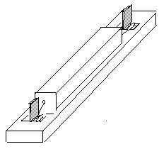
The old home where I grew up had fuses of a simpler kind, rectangular ceramic plugs with brass contacts at their ends (drawing). Usually a plug was held by a pair of clips (shielded from the user) inside a ceramic box: one clip was connected to the input power and held the contact at one end of the plug (drawing). The other clip was connected to the home's circuit and held the brass contact at the other end. The ceramic block had a narrow hole, and the brass contacts had screws attached, between which a piece of "fuse wire" (spools of which were sold in stores) was threaded through the hole. If the circuit got overloaded, the wire would melt somewhere inside the hole (where it could not cause any fire!) and the fuse would be "blown", stopping the current.
To replace the fuse one pulled out the plug, unwound the ends of the broken wire from the screws and discarded them. One now threaded a fresh piece of "fuse wire" through the hole, wound its ends around the two screws and tightened the screws to hold the wire firmly. Then the plug would be replaced. Before replacing it, of course, one needed to find why the fuse blew--otherwise, it was likely to "blow" again, often, at once
Nowadays fuses have been largely replaced by circuit breakers, automatic switches with compressed springs that try to open them up and thus break the connection. A wire holds them closed, but it is part of the circuit: if the current in the circuit is too large, the wire heats up and expands, its grip on the switch loosens and the spring pushes the switch open. Some circuit breakers are screwed into sockets like fuses and have "reset" buttons (allowing the homeowner to replace fuses with them), but most modern ones are plastic and rectangular, and plug into fitting electrical contacts in the "entrance box" where electric power enters the home.
Before doing any work or repair on a circuit in the home, find its connections in the entrance box, the metal box where power enters the house and where all circuit breakers are located. Then disconnect that part of the circuit by resetting its switch from "ON" to "OFF", or unscrew the circuit breaker from its socket. Then check and make sure that the circuit you interrupted was indeed the one with the problem and is now "dead." For this you can use an electricians small "neon light tester" described further below, or an electric meter.
The "blowing" of a fuse or circuit breaker is a sign its circuit was drawing a current larger than the one it was designed to handle. That could be caused by a short circuit somewhere--but not necessarily: an overload will also occur if too many appliances are plugged into the same circuit. If a kitchen circuit is disrupted when a toaster, coffee maker and microwave oven operate simultaneously, it may be a smart idea to delay using at least one of them:
overloaded circuits have also been known to start fires. If an extension cord feels unusually warm, that too is a warning sign.

If no such obvious reason exists, check for a short circuit--e.g. a frayed cord or a short inside an appliance, often announcing its presence by the smell of scorched insulation. Never simply reset the breaker or replace the fuse--if you do, it is likely that it will blow again, putting you back to where you were before (also, the heated element which released the spring may stay warm, and so the breaker refuses to be reset). At the very least, unplug or shut off the electric appliance or light which you suspect causes the problem and then reset. If the light goes out again, you have at least cleared one suspect.
To remember:
Fuses and circuit breakers disconnect an overloaded circuit, protecting the house against fire and often saving appliances before serious damage occurs. In a fuse, a piece of wire safely melts and breaks the circuit; in a circuit breaker, a spring opens up a switch. Overloads may be caused by short circuits--accidental direct connections which draw a large current--or by too many appliances on a single outlet circuit. Whenever they happen, find out the cause and remove it!
|
Electric Shock
Our bodies operate by chemistry, not by electricity. Being saturated in salty fluids such as blood, they conduct electric current well and generally do not channel them into well-defined paths, the way electric and electronic appliances do.
Still, small electric impulses--spikes of voltage--are associated with the beating heart, and are used by a medical instrument--the electrocardiograph (EKG)--to monitor heartbeats and detect irregularities. Electrodes leading to the instrument are attached to specific locations on the body, and the tiny voltages are amplified, recorded and interpreted.
In addition, individuals with irregular heartbeat can be provided with electronic pacemakers. A wire (insulated but with a bare end) is advanced through a blood vessel until its end reaches its assigned position inside the heart, as can be verified by x-rays. It is then connected to a small electric circuit which produces pulses of voltage at selected intervals--often waiting and doing so only if the body has failed to initiate a heartbeat.
The device and its battery--even radio controls for checking out its operation!--are contained inside a plastic capsule, which is connected to the wire and inserted under the patient's skin in the chest area. It uses so little electric current that it may last for 10 years before further surgery is needed for replacing it. Small voltage waves are also associated with nerve action, and the pattern of such "brain waves" picked up from electrical contacts attached to the skull (EEG or Electro-Encephalogram) also has medical uses, e.g. in the diagnosis of epilepsy.
However, the association of heart action with electricity points to a possible problem: a strong "electric shock" to the body may on affect the rhythm of the heart, and the results can be fatal, especially if the flow pattern of the electric current passes the heart. The damage depends not on the voltage but on the size of the current which flows through the body: currents over 20 milliamperes (20 thousandths of an ampere or 0.02 ampere = 1/50 ampere) can be dangerous. Strong electric currents that do not pass the heart can still inflict bad burns.
As noted, human tissue is a good conductor of electricity. The main obstacle to the flow of current through the body is the skin. Dry skin offers some resistance, and these days when most shoes have soles of rubber or plastic, these also add protection, preventing the current from flowing to the ground (which, as was seen, can complete the circuit). However, handling live wires with wet or sweaty hands increases the danger, as does handling electricity while standing with bare feet on the ground. In any electrical work, of course, the first rule is to disconnect the power or separate the victim from the source of voltage, using plastic etc. to shield oneself from "hot" voltage.
The second is to check that power indeed no longer reaches the work area. A small neon lamp connected through a large electrical resistance to two connecting insulating wires ("leads") is often used for such check. Touch one lead to the suspected object, hold the other in your hand: if the object is "hot" a current will flow through the lamp and light it, but because of the enormous resistance, it will be far too weak for you to feel.
Electric fuses and circuit breakers do not offer sufficient protection, because to set them off typically takes 15-20 amperes, while to harm a person takes much less. A recent device offers better protection--the so-called "ground fault interrupt" device often installed in power outlets, in particular in bathrooms, where wet hands and bare feet are most likely to be encountered.
In the usual electric circuit at home, the current flowing in along the black "hot" wire is exactly equal to the one flowing back on the white "return" wire (usually grounded at the entrance to the house). The ground fault interrupt device has an electronic circuit which constantly compares these two currents. As long as they are equal, no action is taken. However, if even a little of the incoming current leaks away to the ground--through leaky insulation or, just possibly, through the body of a careless user--the return current is smaller than the incoming one, in which case the circuit senses the difference and automatically cuts off the circuit. Such devices are sensitive enough to save a person from serious harm.
To remember:
Electric currents can affect the heart's rhythm: in electronic pacemakers small voltage pulses help keep heartbeats regular, but accidental electric shocks can disrupt them and even stop the heart. The human body is a good conductor of electricity: only dry skin and rubber-soled shoes offer some protection. Always disconnect the voltage before working on conductors of house currents. Fuses and circuit breakers may not be triggered by currents large enough to cause bodily harm, but a "ground fault interrupt" device, installed in some outlets, will protect their users from electric shock.
|
Tidbit: Why do switches and circuit breakers click?
...Because they make and break contact very quickly, with a steel spring adding speed to the motion. A switch opening slowly will create a larger spark, a momentary plasma--gas (here, air) hot enough to conduct electricity. It is even possible (though very, very unlikely) that with a powerful current source an electric arc will form, as in an arc welder, bridging the opening gap. An arc (a hot atmospheric plasma) is extremely hot and could melt contacts, but even a spark, though brief, is hot enough to gradually corrode the electrical contacts.
Arcing is a more serious concern in high voltage switches of the electric grid, where switches in the open air open-up wide to break any possible arc, or else, they are immersed in insulating oil.