(E24) Induction and Magnetic FluxThe Electro-Motive ForceRepeating earlier definitions: a vector field is just a region in space where every point is associated with some vector (to a mathematician the term "vector field" also has other meanings). In a gravitational field each point is associated with a vector giving the local force (G?) on one kilogram of mass. Wherever you may be now, it probably points straight down to the center of the Earth!In a magnetic field each point is associated with the local force B on a unit m of magnetic polarity (however we define it). As the compass needle shows, these vectors diverge from the southern polar region and converge in the northern polar region, where they point nearly vertically, though how they continue underground is not observable. And in an electric field at any point the field vector E gives the force on one coulomb of electric charge, if placed at that point. The expectation of "if placed" is in each case inferred from physical laws based on careful observations in the past. Observations suggest yet another "field": given a large volume of fluid with flows in some pattern, each point is associated with some flow velocity field v. The laws of such flows can be complex and even unstable (lapsing into turbulence) and vary depending on whether the fluid is compressible (like air) or not (for practical purposes, water is essentially incompressible). Since the 1700s, a great amount of study has been concerned with the behavior of such "flow fields", including the recent fashion of simulation by large computers, and though such fields may be easier to observe (e.g. by smoke in wind tunnels or sawdust suspended in water), many unanswered questions remain.
To calculate the flux, imagine dividing the surface divited into a large number of little areas (see drawing). At each area dA, we find the velocity v of the water through it (which is a vector), and find the component perpendicular to the are vperp. Each second, the volume crossing dA is a box-shaped volume with base dA and height vperp. Sum them up--we can use a computer for that, or if some mathematical law governs v and S, a suitable formula--and we have the flux of water through the contour S But which surface spanning S should be subdivided? A thin rubber membrane spanning the closed contour could be stretched into many different shapes (two are indicated in the drawing, S1 and S2). The answer is, that as long as there exist no "sources or sinks" in the volume discussed--no spouts, no drains--it makes no difference. Whatever flow through S1 must also flow through S2. The flux is the same through any such surface (as long as the fluid is incompressible). Why bring the flow of incompressible water into a discussion of magnetic fields? Because mathematically they have very similar behavior. One can define streamlines of v which at any point give the direction of the flow, and they behave very much like field lines of some magnetic field B (all this in "empty space" devoid of magnetic materials). And just as we can define the flux of v through some closed contour S, we can define the magnetic flux Φ (capital Greek F or "phi") through it too. Old texts sometimes refer to it as the "number of field lines crossing S" and that was how Faraday interpreted it, but here the concept of magnetic flux will be the same as Maxwell's Back to electromagnetic inductionFaraday found that the induced e.m.f. was only created when conditions changed. A coil and a magnet at rest generate no induced e.m.f.. However, move the coil relative to the magnet--or the magnet relative to the coil--or if it is a electromagnet, vary the intensity of the magnetic field by changing the current producing it--in all these cases an e.m.f will usually result. Faraday's law of induction in all such cases is The direction of the emf is always such that if a closed conducting wire follows the contour S, the magnetic field produced by the induced current opposes the one existing. It is as if nature opposes the change; in this case this is known as Lenz'es Law The MagnetoFor instance, if a bar magnet rotates around a shaft as drawn, and the two coils are connected so that the magnetic flux through them adds up (rather than canceling!), then Φ reverses each half turn, causing an e.m.f. in opposite directions. Halfway between these positions the magnet is perpendicular to the axis of the coils, its field lines skim parallel to the planes of the winding and the total flux through them is zero. 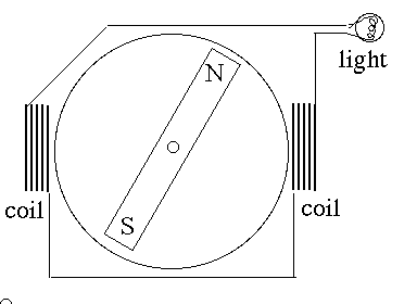
Such a simple generator of electricity is known as a magneto. It is not particularly efficient but is simple and very reliable--which is why bicycle lamps used to get power from a magneto mounted on the "fork" next to the front wheel, rotated by a wheel rubbing against the front tire. Today's bicycles prefer batteries, because with a magneto the e.m.f. and the brightness of the light depend on the speed of the wheel. Note that the rotation of a magneto generates an alternating current (AC). One reason AC is used in our homes is that it is easier to generate: even automobiles generate AC by an "alternator" and later "rectify" it using solid state diodes (described earlier) and use it for charging the battery. Of course, AC also allows the voltage to be stepped up for efficient long-distance transmission. In all this, note that a magneto must abide by the conservation of energy. Turning its "rotor" generates an electric current, flowing in coils whose magnetic force opposes the motion. Overcoming that resistance requires energy, provided by the wheel touching the front tire. A different kind of magneto is found in small gas engines, such as those of lawnmowers. The engine gets its power from a piston pushed when a mixture of air and gasoline vapor ignites rapidly and heats up. The heated expanding gas pushes the piston down a metal cylinder and in the process turns a crankshaft. The top of the cylinder also has two openings controlled by mushroom-shaped valves--one to admit fresh air-vapor mixture, the other to let out the hot burned products. The turning of the crankshaft typically cycles the engine through four "strokes" (two-stroke engines exist, but their modified cycle is less efficient). First the piston rises, the exhaust valve is open and burned gas from the preceding cycle (carbon dioxide and steam) is pushed out. Next the exhaust valve closes and the intake valve opens, and as the piston descends it sucks in a mixture of air and fuel. In the third stroke both valves close and the piston rises again, compressing the fuel mixture. Then when compression is greatest, an electric spark from an insulated "spark plug" ignites the mixture, and its heating pushes the piston in the "power stroke." Electricity is required only at one brief instant in the cycle, but at a high voltage, about 20,000 volts, to break down the resistance of the gas in the small gap between the twin contacts inside the spark plug. The plug is therefore connected to a coil (with additional components, including a switch and a high-voltage transformer), while the flywheel of the mower carries a permanent magnet, which each turn whizzes by the coil and induces the necessary voltage. Car engines operate on the same cycle, but have several cylinders and a more complex electrical system. Engines on small airplanes, however, often use magnetos, deemed more reliable. Old style telephones (also old military field phones) included a crank which the caller turned, activating a magneto which rang a bell at the other end. (E25) Electric Power TechnologyWho invented it? In a 2008 letter, a user of the site "Exploration of the Earth's Magnetosphere" asked:
James Prescott Joule experimented around 1840 with electric motors driven by batteries. According to the New World Encyclopaedia on the internet :
Electric LightThe situation changed rapidly around 1880. First, Thomas Alva Edison introduced the electric lightbulb in 1879. Many independent inventors designed similar lamps, but Edison vigorously promoted his lamp commercially and built DC power stations for his customers. Edison's lamp used a spiral carbon filament, produced by charring a strip of bamboo, in a glass bulb from which all air had been pumped. The lamp which dominated the 20th century was introduced in 1902 later by the Austrian Carl Auer von Welsbach, with had a metal filament (nowadays made of tungsten, which can stand high temperature). Rather than vacuum, filament lamps now containe the inert gas argon, which forms close to 1% of the Earth's atmosphere. Electric motors also turned out to be extremely convenient for transportation. Urban trolleys ("streetcars") spread widely, replacing horse-drawn ones and cable cars like the ones preserved in San Francisco, and elevated steam railroads. Most important, they were the only feasible propulsion for underground urban railroads ("subways"). Many other uses also used them--elevators, cranes and so forth. The "War of Currents"Edison's network provided about 110 volts DC, which fit his lightbulbs and could be provided over short urban distances with no great loss. Nikola Tesla recognized the advantage of AC--in fact using several coils on the same dynamo to generate more efficient "polyphase" AC whose wave cycles were independent. The big advantage of AC was that transformers could convert electricity to high voltage (very efficiently!) and use much less copper in its distribution network. It was first developed in Europe, but George Westinghouse, who got wealthy by inventing an air brake for trains, brought the system to the US and hired Tesla to develop it. Electric lights could operate on either AC or DC, AC motors were at least as efficient as DC ones, and gradually AC prevailed. After a short but nasty public rivalry Westinghouse beat out Edison's "General Electric," in bids for the Niagara power station and the lighting of the 1893 World's Columbian Exposition. In the end General Electric itself switched to AC, guided by Charles Proteus Steinmetz who also developed the theory of AC circuits. IronOne wonders whether electric technology would have evolved as vigorously, if not for the special properties of iron--properties known as ferromagnetism (the prefix "ferro-" signifies iron, though a few ferromagnetic alloys contain none). Iron made possible permanent magnets and compass needles, and generous amounts of it in electric motors and transformers greatly increase magnetic forces. This is because the iron atom is magnetic, thanks to the magnetism of electrons it contains.Actually, many other atoms are also magnetic, but their magnetic axes are usually randomly oriented-- a strong magnetic field will line them up somewhat and get somewhat reinforced ("paramagnetism"), but not by much. Ferromagnetic atoms spontaneously line up with each other, in chunks known as magnetic domains. In a strong field these domains line up magnetically and drastically reinforce the magnetic properties. In some materials--such as steel, hard elastic iron with 0.5-1% dissolved carbon--they can stay lined up and create permanent magnetism. In material like soft bendable wrought iron (low carbon content) they slip back to disorder (they also do so in permanent magnets if sufficiently heated). Lodestones are natural magnets, occasionally found, rich in iron compounds. They are believed to originate when a suitable mineral is struck by lightning, whose strong electric current, though very brief, creates an sufficient magnetic force. . Soft iron concentrates magnetic field lines and therefore produces strong magnetic forces in the areas where they emerge from the metal. Laboratory magnets sometimes have conical pole-pieces with the ends of the cones flat, missing the sharp tip. Such pole pieces are like funnels for magnetic flux, concentrating it to a smaller area to create a more powerful field. Of course, any ferromagnetic concentration of magnetic field lines has a natural limit: when all magnetic domains are lined up, the iron is saturated by the magnetic field and can no longer add to it. Transformers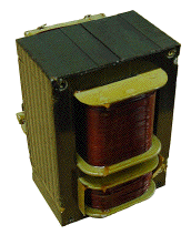 Have you ever opened an electrical transformer? (See image. Disconnected and discarded?) You will have noted several things.
First, the shape of the iron core: it is probably shaped like the letter H, with extra iron bars added across the top and the bottom, and coils that go around the central bar of the H (in the image, that bar is vertical). The "primary coil" wrapped around that bar receives AC and produces in the bar an alternating magnetic field, which is then picked up by the "secondary coil" also wrapped there. In the operating range, the ratio V2/ V1 between output and input AC voltages is also the ratio N2/ N1between the numbers of windings in each coil: Second, notice that the magnetic core is not solid but is built up from many thin sheets of iron, covered with an insulating paint and stuck together. In addition to its magnetic properties, iron is also a conductor of electricity: if a solid core were used, electric currents would circulate not only in the secondary coil but also in the core, limited by Ohm's law and wasting their energy as heat. The paint breaks up such parasitic circuits and prevents currents on all but the smallest scales (where their effect is small). For a similar reason, many other AC devices (e.g. motors) have cores of insulated iron plates. If the device emits a deep hum (at the AC frequency of 60 cycles), some plates may be loose and vibrating, usually a sign of deterioration. And third, you better take care selecting the exact iron alloy you use. Steel can be magnetized permanently: it is not a good choice for a transformer core, expected to reverse its magnetization 120 times each second! In fact, the less your iron "remembers" its previous magnetization, the better it is suited for a transformer core. This "memory" is known as hysteresis ("lag behind"), and is graphically depicted by a plot of B, the magnetic field (or flux) without assistance of the core, against H, the value with such assistance (loosely defined; formulas also exist). The plotted scales for B and H need not be the same. 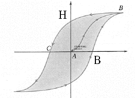
Suppose you start at point A, where the iron is unmagnetized. As the magnetizing current grows, both B and H rise proportionally, but ultimately the magnetization of the iron saturates at point B. From there B and H can still grow, but they go together, with no extra help from the iron core. Past the peak of the AC cycle, the current I causing the magnetization weakens and reverses, but the curve lags behind. At point C, when I=0, B=0 too, but H still "remembers" the old polarity, and will not reverse until the reverse current is large enough. The process now repeats the same variation with the opposite polarity, tracing every AC cycle a closed "hysteresis curve." An energy loss is associated with this forced reversal and can be shown to be proportional to the area inside the curve. The lost energy appears as heating. Large transformers serving the electrical grid need to be cooled, by enclosing them in tight containers (sometimes with cooling fins sticking out) filled with insulating oil. If a transformer in your home starts running hot, perhaps it needs replacing. With all that technology, transformers achieve high efficiency, typically 95%. They are most efficient if the load is small, when the B-H curve approximates a straight line and the operating point just shuttles back and forth along it, leaving little area in the middle. Fluxgate MagnetometersAmong a family of ferromagnetic materials known as ferrites some exist with a very abrupt onset of saturation. Their hysteresis contours are almost rectangular, and saturation always occurs at the same flux density.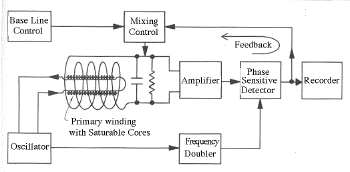
Imagine two identical coils of insulated wire, driven by the same AC current and wrapped around on identical and parallel ferrite rods cores--but winding in opposite directions (the drawing shows the design of an instrument for the NASA Mars mission). Under ordinary circumstances, their magnetic fluxes will be equal and opposite; an additional coil, wrapped around the pair on its outside, will detect no net magnetization, and by Faraday's law of induction, no e.m.f is induced in it. If the cores undergo saturation at the same point in the AC cycle, their magnetic fluxes will still cancel and no e.m.f. is detected by the additional coil. If however an outside magnetic field exists at that location, with a component B1 in the direction of the rods, in one of them it will add to the magnetic flux in its direction, in the other, subtract from it. Therefore one rod will saturate a little ahead of the other in the AC cycle, and the other a little afterwards, creating an e.m.f. signal which can be detected. With suitable design, this signal gives a very sensitive measurement of thc component B1. To detect all three components, of course, requires 3 pairs of rods in mutually perpendicular directions. The pair of rods can also be replaced by a ring core of ferrite (see below), one side of which has N clockwise turns and the other N counterclockwise ones (as seen from the same side), of the same insulated wire. 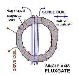
Several people pursued this detection method in the 1930s, but the most successful was probably Victor Vacquier. Until then, measurements of the magnetic field of Earth relied on some sort of suspended magnetic bar or needle: the fluxgate instrument allowed measurements to be pursued aboard airplanes and ships, and later aboard spacecraft as well. Warships could detect iron submarines under water (one reason the Soviet Union switched to the metal titanium). Magnetic surveys could be carried out at sea, discovering conclusive evidence of plate tectonics and the record of reversals of the north-south polarity of the Earth's magnetism going back many millions of years. In space fluxgates monitored the very weak magnetic field of interplanetary space and also surveyed magnetic fields of other planets. The sensitivity of such instruments extends to fields weaker than a millionth of the Earth's surface field. For another interesting story of the use of such an instrument, see "About Electronic Magnetometers and about Smoking." (E26) AC Impedance
Going Beyond Ohm's LawWith alternating current (AC), what happens to Ohm's Law? For pure resistors (e.g. those in simple bread toasters) Ohm's law is the same for both AC and DC currents, with the usual caution that here is not a fundamental law of nature, just an approximation which holds for certain materials and conditions. Fluorescent lamps don't go by it, and even the filament of a flashlight bulb increases its resistance fivefold when glowing (which helps switch it on quickly, because the initial current is 5 times larger). Nonlinear elements which protect computer power inputs don't obey Ohm's law, either: in usual operation, they act like insulators, but their insulation collapses when a large voltage spike occurs (e.g. when lightning hits a power line), protecting the device.With AC currents resistors obey Ohm's law, but in addition, new circuit elements also appear, in particular capacitors and inductors (magnetic coils, including transformers). As already noted, a capacitor will let a varying voltage pass through it. If a positive voltage rises on one plate or set of plates in the capacitor, the other plate will at first match it with an equal rise (until enough current has flowed to charge the capacitor). This makes the current effectively go through, and with AC such variations occur all the time. A capacitor's ability to transmit AC voltage depends on the speed of variation: radio-wave frequency are transmitted quite easily (the wave duration is too short for the circuit to supply much charge), sometimes evev unintentionally when circuits operate close to each other (your computer probably shields some of them inside grounded aluminum boxes, to block such "pick-up"). House-current AC varies relatively slowly, 60 cycles per second, and uses larger capacitors--but smaller ones serve aboard ships and airplanes, with 400-cycle AC). Constant voltages of steady DC are, of course, completely blocked. Radians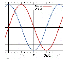 A "simple" AC voltage rises and falls in a wave like a the trigonometric sine function (red) or cosine function (blue, differing only by a horizontal shift). A location on the wave at any instant is called the AC phase (x in the graph) and is often measured in degrees, 360° for a full cycle, a system inherited from ancient Babylonians, who noted that the position of the Sun in the sky, (relative to the background stars), makes each year a full circle and advances each day about one degree. Then if f is the AC frequency in cycles per second, during a time t the functions
go each second through f cycles. In mathematics, however, angles are frequently measured in radians, units equal to about 57°. One full rotation contains 2 π radians, where π=3.1415926... is the ratio between the circumference of a circle and its diameter (yes, I have a super motorbike to travel about the roads foolishly...). It may seem strange to measure angles in units of which the circle does not even contain a whole number and which can only be used to some approximation. However, radians give mathematical advantages, e.g. formulas such as where 3!=6 ("three factorial") is produced by multiplying all integers up to 3, also 5!=120 by multiplying up to 5, and so on. That formula holds in radians; in texts using degrees, each x on the right must be multiplied by 2π/360. Following most texts, we work here in radians (except that phase angles are sometimes in degrees), and in place of the frequency f cycles-per-second, use the "angular frequency" ω = 2 π f radians-per-second, denoted by the lower-case Greek letter omega (upper case Ω is used for "ohms"). AC Impedance--CapacitorsA capacitor of C farad with charge Q coulomb stores electric energyThe necessity to "load up" the charge in the beginning of the AC cycle (when the sine function starts fom zero) and then "unload" it again impedes the flow of current. Circuit analysis therefore includes an impedance A capacitor with large plates (and large C) has a smaller impedance, since it lets AC pass more easily--if a positive charge is added on one plate, a corresponding charge quickly accumulates on the other plate, even at moderate voltage changes, and the voltage signal continues on the other side. And the impedance of a capacitor decreases as the angular frequency ω grows, meaning a higher frequency can more easily propagate through space than a lower one. Steady DC with ω=0 cannot propagate at all but is stopped by the capacitor, which for DC is just a break in the continuity of the circuit. AC Impedance and Admittance--Inductors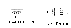 An opposite behavior is observed in current carrying coils, where every AC cycle need invest energy to build up a magnetic field, only getting the energy back when the current drops and reverses. This energy-storing property is called inductance (or "self-inductance") and is especially noted in coils, magnets and transformers: just as capacitance stores electric energy, inductance stores magnetic energy. Its unit is names the henry
after Joseph Henry who invented the practical electromagnet, and inductances in such units are usually denoted by the capital letter L. In analogy to an earlier equation, an inductor of L henry carrying a current of I amperes stores magnetic energy
An opposite behavior is observed in current carrying coils, where every AC cycle need invest energy to build up a magnetic field, only getting the energy back when the current drops and reverses. This energy-storing property is called inductance (or "self-inductance") and is especially noted in coils, magnets and transformers: just as capacitance stores electric energy, inductance stores magnetic energy. Its unit is names the henry
after Joseph Henry who invented the practical electromagnet, and inductances in such units are usually denoted by the capital letter L. In analogy to an earlier equation, an inductor of L henry carrying a current of I amperes stores magnetic energy
If you suddenly break a circuit which includes a large inductance, this may create a big spark from the high voltage generated by the magnetic energy, as the current tries to keep going.
The impedance of a device with stored magnetic energy (coil, electromagnet, transformer, electric motor) has the opposite frequency dependence than capacitance. It is low at low frequency--for DC, only the ohmic resistance of a coil resists the current--but gets larger the more rapid the change, e.g. the higher the frequency. Its value is
The graphic symbol for an inductance is a spiral, denoting a coil--the spiral has a few parallel straight lines next to it if the coil has an iron core, and two parallel coils with a bundle of straight lines in the middle to denote an iron-core electric transformer. Just as a resistance R is mirrored by conductance 1/R, so impedances have corresponding AC admittances Cω and 1/Lω . Where complications beginIt would have been nice if we could carry over all the formulas of resistor circuits to capacitors and inductors. In some simple cases, that is possible: two capacitors (C1, C2) in parallel act like a single capacitor (C1 + C2), and two inductors (L1, L2) in series are equivalent to a single one (L1 + L2). The complimentary equations also hold, but please note that capacitances in (series, parallel) add up like resistors in (parallel, series).Things grow complicated in circuits including both types, and also resistors. Impedance not only depends on angular frequency ω, it also can shift the phase of the AC wave forward or backward in time (or in angle, if you wish). The sine waves of volts and amperes may shift their starting points in the cycle and that, at the very least, reduces the power transmitted. Such shifts can be represented by replacing sin ωt with combinations of sines and cosines, or by a mathematical scheme which requires "complex numbers", a set of mathematical objects broader than "ordinary" numbers, including all of those plus "imaginary" parts proportional to multiples of i=√–1 (in texts on electricity, it is often replaced by the letter j, reserving i for current). For this introductory overview, that would be going too far; you may look up here, a file which is part of an extensive course on electricity. Let us just note that a mere shift of phase (when ohmic resistance is negligible) absorbs no energy, it just mixes up some of the waves because of temporary storage of electric energy (in capacitors) or magnetic energy (in inductors). Such combinations can serve as frequency filters, useful (for instance) when you try to tune in a radio or TV broadcast of a certain frequency while rejecting all others which are "on the air" at the same time. The Crystal RadioWhen tuning a radio, the knob which you turn is usually connected to a variable capacitor, whose symbol is a pair of parallel lines (like any capacitor) crossed by a slanted arrow. Like any capacitor, this one too has two sets of plates, separated by empty space or by an insulating "dielectric material." One set is fixed (and often grounded), while the other one is connected to the shaft of the tuning knob. By turning the knob, you change the extent to which the plates overlap--and since only the overlap (essentially) contributes capacitance--this changes the effective capacitance. 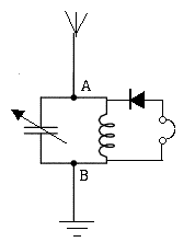
Consider a capacitor and inductor connected "in parallel" between points A and B. If the inductor has negligible ohmic resistance, for a steady DC (ω=0) it essentially short-circuits A to B, so their voltage difference is zero. On the other hand, for DC the capacitor is an open gap and can be omitted from the circuit. Going to the other extreme, a high radio frequency (say, ten million cycles per second), the capacitor places a very low impedance between A and B--it acts like a short circuit for the radio frequency. The coil on the other hand has such high impedance that we may just as well ignore it. At these extremes of the frequency range, the impedance between A and B is near zero--like a direct connection which allows no voltage drop. But not in a range of ω in-between, where both capacitance and inductance have non-zero impedance. In fact, somewhere in the middle range a resonance exists and the impedance is large, so that if B is earthed while A receives a large AC wave, an AC voltage can build up between these points. Jump ahead a few steps. Suppose A is attached to a wire in space, suspended from insulating supports and subject to whatever electric fields exist there. If the location is near a strong AM radio station, it can capture some of the radio signal. The wire then becomes a receiving antenna, marked in the diagram by several short lines forming moderate angles (like a schematic broomstick). If the variable capacitor is now adjusted so that the resonant frequency f of the circuit matches the frequency of the transmitter, the voltage of A will rise and fall with the radio signal. If the resonance is elsewhere, the impedance between A and B is small and only a small signal voltage exists between A and B.
However, we not only want to detect the radio-frequency signal, but also decode the sound signal it carries. One of the earliest methods of encoding sound was amplitude modulation (AM), taking a wave with fixed frequency and modulating its height to follow the electric signal from a microphone. Car radios still receive AM radio, and so will the outdoor antenna we described. If we now insert a solid state diode like the one converting AC to DC in section #16, the earphones may respond to the average voltage, filter away the radio frequency and leave speech or music only. You will then have created a "crystal radio" like the one built by schoolboys in the early days of radio. Reliable "solid-state rectifiers" did not yet exist, but certain crystals touched by thin wire "whiskers" had similar properties, and persistent amateurs could sometimes hear broadcasts. It wasn't a good radio receiver then, and even now, with a solid state rectifier, it performs poorly, because the earphones have no energy source except the captured part of the radio wave, which tends to be quite weak. Regular radios amplify the weak signal, using the energy of batteries or of power supplies like the one in section #16. But the crystal radio was one beginning. Radio Waves themselves will be discussed later. For now, just take for granted that all space around you contains oscillating voltages, broadcast by countless antennas in many frequencies, all over the country and the world. (E27) Electro-Magnetic Waves, at last!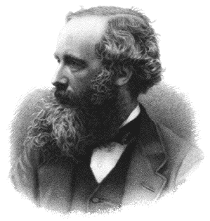
James Clerk MaxwellJames Clerk Maxwell was born in Edinburgh, Scotland, in 1831 when Faraday also discovered electromagnetic induction. His father was a well-to-do attorney, but his mother died when he was young leaving him the only surviving child in the family. He studied in the Edinburgh Academy, a bright lad with interest and talent not only in mathematics and sciences, but also in drawing and poetry. Later he attended the Universities of Edinburgh and Cambridge, and from early age did original research and published articles. In 1856 he joined the faculty at Marischal (later the University of Aberdeen) and in 1860 moved to Kings College in London, where he got to know Faraday and appreciate his work.Faraday's grasp of physics was intuitive, without higher math. Maxwell had both math and the intuition, and he therefore tried to understand Faraday's vision and translate it into mathematical terms. He did much more in his short career (he died of cancer at 48), such as investigation into the theory of color and in particular the theory of gases. An ideal gas may be viewed as a collection of individual molecules moving randomly, with an average speed that increases with temperature, colliding elastically and frequently. Because of these collisions, some molecules gain energy above the average, others lose it, creating an average distribution found by Maxwell and still named the Maxwellian. From his theory he deduced viscosity, mean path between collisions and many other properties. He even worked out the theory of the radiometer, a vertical "windmill" with vanes black on one side and white on the other, spun up in an evacuated glass bulb by a beam of light. The spin is often attributed to light pressure, but the effect is much more complex. Electric and Magnetic Fields, and Maxwell's EquationsHis greatest success, though, were "Maxwell's Equations" a set of rigorous mathematical relations confirming Faraday's guess that a transverse electro-magnetic wave could exist, and that light was probably such a wave. He assembled the equations of electricity and magnetism--the basic ones which did not depend on properties of materials, but held even in a vacuum:
Maxwell expressed each of these statements in a suitable mathematical form, but we skip that since it would require tools of differential calculus of three-dimensional quantities and of vectors. Number #2 is true even though we do observe magnetic poles on bar magnets; however, the existence of such paired poles can also be explained by a suitable distribution of currents. It was Ampére who originally pointed out that if each atom included a small circulating current ("Ampére current"), lining up the axes of those currents would produce the same bulk magnetism as is observed in bar magnets and lodestones. There remains a certain vagueness in all this: which here are "real" objects and which just mathematical abstractions? Electric charges and electric currents are presumably real, associated with the matter in which they reside--and if isolated magnetic poles existed, they might be deemed "real" too.
On the other hand the "electric force" and the "magnetic force" at a point in empty space seem somewhat abstract: unless an electric charge or electric current are actually located at such a point, it did not seem any different from any point in empty space. And yet Maxwell ultimately held that they were not quite empty. A point associated with a possible electric force was endowed with an "electric field E," a vector with strength and direction, implying that if a charge q was placed there, it would sense a force qE. Similarly, an otherwise empty point would be endowed with a magnetic field B if a force mB would be sensed by a magnetic pole m there, if such poles existed--or a force I(dlxB) on a current I in a short length of conductor dl (a vector), as explained at the end of The Displacement CurrentWaves in general are associated with a periodic interchange of energy:
The two were linked, but a gap seemed to exist. By equation (4), varying the magnetic field B changed the magnetic flux, producing a changing electric field E. If a transformer coil is placed around the changing flux, this E will create a changing current I, which may create more of the variable magnetic field B. But you need a changing current I: if no coil is placed in that space--no current is expected. And current is what creates a magnetic field B. A changing electric field E was not a source of magnetism. Except..... for that strange way an AC current can flow across a capacitor, even if the space between the plates is empty. Given two parallel plates A and B, if the voltage at A changes, for the short interval before the charge (and energy) of the capacitor can change, the voltage at B follows the one on A. At least for that very short time, a voltage change does propagate across the gap. That may be generalized to an AC current, provides it changes fast enough. if the input is an AC voltage with angular frequency ω, the current flowing across the gap is proportional to ω, too. The frequency f associated with a light wave can be calculated from its wavelength λ in optical experiments and from the velocity of light c: f=c/λ One gets quite high frequencies, at which this unusual AC current might cross empty space quite easily. Maxwell named it the displacement current. Does the displacement current have the same properties as current conducted by a wire--in particular, the ability to create a magnetic field B? Maxwell guessed it did, and so a high frequency AC electric field E could drive a high frequency AC magnetic field B across empty space. Equations could then be written in which a wave of E and one of B alternate, perpendicular to each other and (for both) to the direction in which the wave advances ("the ray of light"), with a velocity which in vacuum equals c. In ordinary light E can be in any direction perpendicular to the ray, but polarized waves, where (say) E is always in the same direction (and B perpendicular to it) are also possible
The FulfilmentIn 1884 John Henry Poynting proved that if electro-magnetic waves existed, they would be able to transmit both energy and momentum to material which intercepted it, which seemed a valid test of their reality. The energy is evident in any object heated by bright sunlight, and the momentum showed itself in the pressure of sunlight measured in 1902 by Lebedev in Russia. It is now considered for solar sails in deep space. Maxwell died of stomach cancer in 1879, and who knows what else he may have contributed, had he lived to a ripe old age. One important question remained: how could an electromagnetic wave be generated? Its details occupied many scientists in the 50-60 years that followed and led to an entire new insight on physics at the atomic scale, now known as quantum theory. Hot solid substances radiated a continuous spectrum whose frequency rose with energy--from cherry-red hot iron in a smith's forge, to the bright yellow light of the filaments of Edison and Welsbach--to the even hotter electric arc of Humphry Davy, whose light contained a lot of ultra-violet (the reason arc welders wear special masks). The hotter the source, the shorter the wavelength, but for a while scientists did not understand why. Glowing gases (e.g. in fluorescent lights) behaved differently. When excited by high voltages, they preferred to emit light at selected frequencies ("line spectrum"), accurately defined and characteristic of the emitting substance. Here was clearly a lot of information, and it took a complete overhaul of physics to figure it out; see here, here and here for some details. All these involved processes on an atomic scale, where electro-magnetic circuitry does not exist and where (as it turned out) laws of physics are markedly modified. But how to create electromagnetic waves using known electrical equipment in the laboratory? Heinrich Hertz in Germany proved mathematically and confirmed by experiment in 1886 that the high-frequency AC in a loop antenna (generating a magnetic field) or an antenna composed of two opposing rods (a "dipole antenna," with the circuit closed by the displacement current) could generate an E-M wave. It was already known that lightning and sparks produced currents which oscillated very rapidly, a mixture of high-frequency AC (even now, on an AM radio during a thunderstorm, you can hear the crackling of "static" due to lightning, regardless of the station you are tuned to). 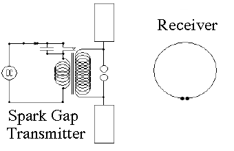
Hertz created a high frequency spark discharge by generating a high voltage by transformer and discharging it through an "antenna" (he tried both kinds) with a spark gap in the middle (see also here). The oscillations between a charged capacitor and an inductor can also broadcast an E-M wave. Hertz was mainly interested in proving the generation of electromagnetic waves; little did he suspect that by 1903 Marconi would send radio signals across the Atlantic ocean, or that in 1912 the sinking "Titanic" would radio for help after colliding (at full speed) with a drifting iceberg. (E28) Electric Communication
For thousands of years the preferred mode of rapid communication was man on horseback. Herodotos wrote of the messengers of the ancient Persian empire
The Electric TelegraphThe invention of the electromagnet made electricity the method of choice in long-distance signaling on land. In Britain, Cooke and Wheatstone developed a system with 5 insulated wires, each of which could move a magnetic needle: any simultaneous shift of two needles encoded a letter of the alphabet. However, the most successful telegraph was developed by Samuel B.F.Morse, a US artist. Morse (1791-1872) studied at Yale and in Europe and became a quite successful painter of portraits. His most famous oil painting (1821-2) was of a session in the old US House of Representatives in the Capitol. It is a large painting with many of the faces of representatives recognizable, and was exhibited around the country for a fee; the original is now on display at the Corcoran Gallery in Washington and a small version is displayed in the same hall, which now houses statues of famous Americans. Morse learned about electromagnets on a sea voyage in 1832. Wilhelm Weber and the mathematician Carl Friedrich Gauss had constructed a magnetic telegraph connecting their lab (later downed by lightning) and Morse decided to develop a telegraph of his own, using a single wire and return through the ground. He devised the Morse Code encoding letters, numbers etc. as combinations of "dots and dashes", short and long pulses fed over the telegraph line to a distant receiver. There the electromagnet placed marks on a paper tape, slowly advancing past it by clockwork. For instance, 3 dots make the letter "S", 3 dashes the letter "O", so ...--- ... spells "SOS" and is the universal distress code ("Save Our Ship" or "Save Our Souls"). 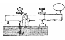
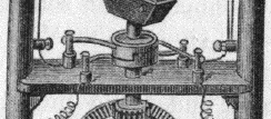
The Morse code is still widely used by amateurs, by some simple signaling devices and in emergencies. The transmitter is the "Morse key" (see image), a bar pivoted in the middle, with a knob at one end. That end serves as a switch normally kept open by a small spring, while a screw at the other end limits the opening distance of the switch. The hand of the operator on the knob closes it for short or long intervals, and an electric battery provides the current. 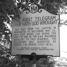
Congress in 1842 finally authorized a telegraph line from Washington to Baltimore, operated after 1844 (the plaque shown is along hwy. 1 in Beltsville, south of the Muikirk Rd. overpass). The telegraph spread rapidly (especially along railroad lines) and Morse's elaborate paper tape instrument was soon dispensed with when telegraph operators learned to listen to clicks of the magnet and decode the message by ear (in the early days, the "dash" in the Morse code actually resembled today's "double click" on the computer mouse). Thomas Alva Edison, the inventor, started his career as a telegraph operator. In the US Civil War the telegraph was used extensively--even to communicate from tethered observation balloons to the ground. Incidentally, electricity was also used by the Confederate military to set off underwater mines, known as torpedoes. When Admiral David Farragut, in the battle of Mobile Bay, said "Damn the torpedoes... full speed!" he ordered his ships to continue the attack even though one has been sunk by a mine. Russia used similar mines in the Crimean war. The cigar-shaped underwater missile known as the "Whitehead Torpedo" and guided by gyroscope was developed later in Europe. Soon after the telegraph was invented, undersea telegraph cables were laid, starting with an 1850 link between England and France. In 1857-8 a cable was laid between Europe and the America, but it operated very slowly and soon failed. Another was laid in 1866, but the capacitance and inductance of the long line distorted the signal--what was sent out as crisp square blocks arrived arrived with profiles like heaps of sand. William Thomson--later Lord Kelvin--was active in advising the cable construction, and later Oliver Heaviside and Michael Pupin modified the cable to reduce signal deterioration. Cables in the 20th century contained "repeated" amplifiers to preserve the signal, while modern technology introduced lasers and fiber optics, also communication satellites. (Click here for the last message sent by Samuel Morse, and the statue in his honor in New York City). The TelephoneThe credit for inventing the telephone, transmitting speech by electricity, is still being debated. A patent was granted in 1876 to Alexander Graham Bell, a teacher to the deaf, and his system ultimately prevailed in the patent courts. A simple "dynamic" telephone has a receiver with a diaphragm, set to be vibrated by the speaker's voice. Attached to it was a lightweight wire coil surrounding a magnet, free to move without touching it, and the vibration generated an induced current. The current ultimately reached a somewhat similar set-up in the earpiece, except that here the coil was vibrated by the current it received, causing the diaphragm to oscillate and generate a sound. The use of such a "dynamic" phone spread rapidly, but it had two limiting factors. One, the energy transmitted was limited by the electricity the input sound could generate. This was overcome in 1877 by the carbon granule microphone of Thomas Edison and Emil Berliner. An electric battery fed current through a small box containing carbon granules in loose contact, which a voice-activated diaphragm compressed and relaxed. This affected the resistance of the granules and created a signal which transmitted voice, though its quality was mediocre. The energy was now produced by the battery and the signal was large enough that sometimes the receiving detector was just a loose thin iron plate, attracted by an electromagnet. After the invention of the vacuum tube amplifier (later replaced by solid-state devices) the signal could be easily amplified further, and with better quality. A related invention by Edison was the phonograph, recording music and speech through a groove in a cylinder rotated by clockwork. A sharp stylus attached to a diaphragm created the groove, and the sound was encoded by tiny wiggles in it. Later (1887) Berliner replaced the cylinder by a disk of hard rubber, made by hot pressing from a master recording. The reproduced sound came from another diaphragm, attached to a needle which tracked the groove. At first this was a purely mechanical device, without electricity. The clockwork had to be wound up anew every few minutes and the sound was rather tinny. Electronic amplification improved the sound and the volume, plastic records made possible long-playing records (about 45 minutes instead of 3), and later magnetic tapes and disks, as well as laser disk players and electronic memories, replaced the technology and improved the recording of sound. The second limitation was that telephone users needed a network. With early telephones, each user had a line to the switchboard and a hand-cranked magneto, attached to the line but isolated from the sound transmission by capacitors. To make a call, the user gave the magneto a few turns, ringing a bell in the switchboard office and raising an iron "flag" held by an electromagnet, identifying the calling line, or in later versions turning on a small electric light. The operator (usually a woman) would then use a cord to plug her phone into the line and ask whom to connect, then shift the cord to the receiving party and ring the bell there. When the call ended, the 'flag" dropped or the light went out, and the operator pulled out the connecting cable. Later this was replaced by massive automatic machinery based on magnetic relays. A relay is an electric switch closed by an electromagnet--probably invented by Joseph Henry and allowing a small input of energy (in the magnet) to control a much larger current (in the switch). The user inserts a finger in one of to holes around a dial and pulls; a spring then returns the dial to its starting position, producing 1 to 10 clicks (depending on the hole the finger pulled). A motor in the automatic switchboard then rotates a "stepping switch" one position for every click, encoding a number 1 to 10 (marked 0 to 9). Four pulls on the dial can thus encode numbers up to 10,000, activating 4 switches to connect the proper phone line. That was then--nowadays solid state circuits and computers do all the switching and more. RadioThe creation of radio waves by Heinrick Hertz was just the first step. Hertz died at a young age, but the Italian inventor Gugliemo Marconi successfully expanded his invention and turned into a commercial success (earning a Nobel prize along the way). Initially, radio waves were detected by coherers, glass tubes filled with metal shavings. Radio waves made the shavings cling together, increasing the tube's electric conductance and thus able to detect signals in the Morse code (and also detect lightning, by Aleksander Popov in Russia in 1894).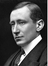
Marconi experimented with radio devices, improved them and increased their range. Somewhat unexpectedly, radio signals (unlike light) were found to be able to travel beyond the horizon (especially at night), suggesting to Oliver Heaviside that they were reflected by an electrically conducting layer in the high atmosphere. "The Heaviside Layer" is now known as the ionosphere, created by sunlight of very short wavelength, with the lowest "D layer" (which absorbs lower frequencies) recombining after sunset. Using a ship Marconi studied the range and worked to extend it, and in 1903 his shore station at Cape Cod, Massachussetts, detected transmissions from England (the remains of the station are now part of a National Seashore Park, but were relocated further inland after parts of the shoreline were washed away in storms). His company employed Reginald Fessenden to build high-frequency spark transmitters for ships, from which came the nickname "Sparks" for naval radio operators and the German verb "funken" (to spark) for wireless communications. Another employee was David Sarnoff, who reputedly picked up distress signals from the sinking "Titanic" and who later headed RCA, the Radio Corporation of America. Radio advanced tremendously after Lee Dr Forest in 1906-8 introduced his triode vacuum tube which controlled a current emitted in vacuum from cathode heated by an electric filament. The electrons were collected by an "anode" at a higher positive voltage (which attracted electrons), and could be modulated by a spiral wire or "grid" placed between the two. A positive grid reduced the flow of electrons, a negative one helped draw them out, making possible amplifiers of sound and of radio waves (in both transmitters and receivers). By feeding part of the signal back to the grid, through a filter tuned to one frequency, a strong radio "carrier wave" could also be obtained, on which the sound was encoded.
Since then, vacuum tubes were replaced by "solid state devices" based on crystalline silicon with suitable impurities added. The frequency of radio was gradually increased, leading to radar, microwave ovens, communication satellites and radio telescopes. All these however are beyond the scope of this introduction.
End of this Exposition |
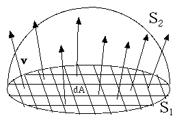 Let us concentrate on water, assumed to be incompressible. If we trace by a thin wire (or imagine doing so) some closed line S ("closed contour") in a fully defined 3-dimensional water flow, can calculate how many liters of water cross the surface spanned by of S each second. That would be the flux
(of water) through S.
Let us concentrate on water, assumed to be incompressible. If we trace by a thin wire (or imagine doing so) some closed line S ("closed contour") in a fully defined 3-dimensional water flow, can calculate how many liters of water cross the surface spanned by of S each second. That would be the flux
(of water) through S.